ELECTROLYTIC SYSTEMS FOR THE TREATMENT OF SOLVENT-CONTAMINATED WATER
E.A. Betterton, 1 R.G. Arnold,2 Z. Liu,2 I. Diaz2, G. Chen2
1Department of Atmospheric Sciences, University of Arizona, Tucson, AZ 85721 (520) 621-2050; 2Department of Chemical and Environmental Engineering, University of Arizona, Tucson, AZ 85721
Abstract
Electrolysis has proven to be a useful method for dehalogenating ground water contaminants such as carbon tetrachloride, CT, (by reduction at a cathode) and trichloroethene, TCE (by oxidation at an anode). High rates are observed in a laboratory scale two-compartment, three-electrode batch reactor. Typically, millimolar concentrations of aqueous-phase targets can be dehalogenated in minutes to hours. Depending on the nature of the target compound and the working electrode (cathode or anode; Fe, Ni, Cu, Ebonex, etc.) dehalogenation can proceed through to the parent alkane (by reduction) or to CO2 (by oxidation) in high yields.
In general, reaction rate increases as more extreme electrode potentials are applied. The rate is ultimately limited by mass transport. CT reduction rate increases modestly with [H+] in the pH range 2.0 to 5.0 but above pH 5.0 dehalogenation rate is essentially pH-independent. Reduction is first-order in CT. Products include chloroform, dichloromethane, methane, OH-, and Cl-. TCE oxidation is pH-independent (1.6<pH<11) and first-order in TCE. Major products include CO2, CO, Cl-, and ClO3-. Satisfactory carbon and chlorine mass balances indicate that all major transformation products were accounted for.
KEYWORDS: electrolysis, reduction, oxidation, dehalogenation, remediation, solvents, groundwater, TCE, carbon tetrachloride
Introduction
Over the past 30 years a number of diverse abiotic systems for promoting dehalogenation of organic solvents have been investigated (see Vogel et al., 1987; Wood et al., 1968; Schrauzer and Deutsch, 1969; Criddle and McCarty, 1991; Kuhler et al. 1993; Matheson and Tratnyek, 1994; Cheng et al., 1997; among others). Those based on chemical reduction by zero-valent metals are particularly appealing in terms of their kinetics and apparent simplicity. For example, Sweeney and Fisher (1972, 1973) used granular zinc to enhance the degradation of pesticides, while Gillham et al. (1993) explored the chemistry and limitations of zero-valent metals as agents for the reductive dehalogenation of halogenated methanes, ethanes, and ethenes. The minimum reactive system consisted of the elemental metal, distilled water, and the target compound. Among the several metals tested, iron and zinc proved the most reactive. Half-lives vary considerably for the iron system, but are generally shorter for heavily halogenated compounds (e.g., 13.6 h for trichloroethene (TCE) vs. 106 h for vinyl chloride under similar conditions).
Gillham and O'Hannesin (1994) also described dechlorination in column reactors using a mixture of silica sand and iron filings. Other column studies utilizing Fe have been conducted to investigate remediation of TCE (Clausen et al., 1995), and a mixture of TCE and dichloroethylene (DCE) isomers (MacKenzie et al., 1995).
Here we describe a logical extension of the zero-valent metal work in which the metal becomes the cathode in an electrolytic cell. This has two major advantages. First, the reaction rate can be boosted simply by applying an electric potential of a few volts to the electrode, and second, the metal is inherently cathodically protected from corrosion. We have also studied dehalogenation at the anode. In this case metals tend to be unsuitable because they are easily corroded under the positive potentials applied. Instead, an electrically conducting ceramic anode (Ebonex, Ti4O7) was used. Although a wide variety of target species was studied, this paper emphasizes a) the reductive dehalogenation of CT at Fe, Cu and Ni foil cathodes, and b) the oxidative dehalogentaion of TCE at an Ebonex anode.
Methods and Materials
Materials
HPLC-grade solvents (Aldrich) were used as received. Methane was 1004 ppm(v) and 1% (v/v) in N2 (Aldrich). Milli-Q water (Millipore, 18 MW cm) was used to prepare all solutions which were deoxygenated by purging with helium (U.S. Airweld, > 99.995%), when necessary. Metal foil and wire used for constructing electrodes (Johnson Matthey) were Puratronic grade, 99.99%. The 2×8.5×0.25cm (20 cm2 surface area) Ebonex wafer (Electrosynthesis Corp.) is chemically resistant to oxidation yet electrically conductive. Background electrolyte was either 0.1M Na2SO4 (reduction) or 0.05 M KNO3 (oxidation). The pH was controlled by addition of HCl or NaOH with an automatic burette (Metrohm, 665 Dosial + 614 Impellant). At pH< 6 solutions were unbuffered but at pH > 6.0 they were buffered with 5mM tris(hydroxymethyl)aminomethane (Sigma) for reduction studies.
Electrolysis Cell
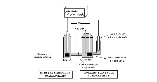
The cell is based on that of Criddle and McCarty (1991). It consists of a two-compartment glass vessel (Electrosynthesis Corp.), with cathode and anode compartments separated by a Nafion 117 cation-permeable membrane or a sintered glass disk (Figure 1). The working electrode compartment was fitted with ports for purging the solution, gas- and liquid-phase sampling, acid/base addition, pH- and working electrodes, and a side chamber for a reference electrode (saturated Ag/AgCl; Orion 90-02 with outer sleeve removed). The 370 mL working electrode compartment was completely filled with liquid when it was necessary to avoid possible mass transport limitations at the gas/liquid interface. A Teflon-coated magnetic stir bar was used to continuously mix the contents.
When studying cathodic reactions the anode was 25x21x0.1 mm Pt foil. Cathodes consisted of 25x21x0.1 mm metal foil attached to 50 mm Ag wire. Glass sheaths, epoxied in place, enclosed the wire. The cathode surface was cleaned immediately prior to each experiment by lightly sanding with 400-grit sandpaper. Organics and residual grit were then removed by rinsing with dilute hydrochloric acid and acetone before rinsing with water and drying with lens paper.
When studying oxidation reactions the cathode was a graphite rod (1.27 cm D×7 cm L) and the anode was Ebonex.
A potentiostat (Electrosynthesis, Model 410) and 24-volt power supply (Harrison Laboratories, Model 6201A) were used to set the working electrode potential. Voltages are reported relative to the standard hydrogen electrode (SHE). Circuit current was determined indirectly by measuring the potential difference across a 1- resistor in series using a high impedance digital voltmeter. A glass combination electrode (Brinkmann 39843) was used for continuous measurement of pH in the working electrode compartment.
Electrolysis Experiments
Target compound, e.g., CT or TCE, was injected directly into the electrolyte which had been previously deoxygenated, if necessary. When the liquid-phase concentration had stabilized (typically after 30 minutes stirring), the electrode potential was set to satisfy experimental objectives. The reactor was covered with aluminum foil to exclude light.
Liquid-phase and/or head-space samples were drawn at intervals and analyzed by gas chromatography (after pentane extraction of the aqueous phase). Eluted peaks were identified by comparison with authentic standards and confirmed by GC-mass spectrometry.
Experiments were run at selected combinations of working electrode potential, EW (-0.4 V to -1.4 V cathodic; +2.5 to +4.5 V anodic) and solution pH (2 to 11). The potential difference between the working and counter electrodes was normally 2 to 7 V, depending on experimental conditions. Experimental data included time-dependent concentrations of target, products of dehalogenation, cell current and acid/base added to maintain pH. Rates of disappearance were normally first-order in target species. Linear regression of the semi-log plots (n > 15) yielded the first-order rate constant, e.g. kCT (min-1) in Figure 5. This constant has not been adjusted for electrode surface area or reactor volume. The specific rate constant, e.g. kSTCE (cm min-1) in Figure 6, is calculated from: kSTCE = kTCE/(electrode area/reactor volume).
When necessary, volatile products such as CH2Cl2 and CH4 were determined by sampling a small residual head space left in the working electrode compartment. Henry's law equilibrium was assumed (MacKay et al., 1993).
Results
Reduction
The results of a typical CT dehalogenation experiment (Fe, EW = -0.8V vs. SHE, pH 7.0) are shown in Figure 2. CHCl3 was the primary product observed over the first 10h with increasing yields of CH2Cl2 and CH4 over longer periods. Dehalogenation was first-order with respect to CT. A good carbon mass balance was obtained (±10%) suggesting that all major reaction products were accounted for. Oxygen was liberated at the anode. The cell reaction is:
CATHODE: CCl4 + H+ (H2O) + 2e- = CHCl3 + Cl- + (OH-)
ANODE: H2O = 2H+ + 1/2O2 + 2e-
CELL: CCl4 + H2O = CHCl3 + H+ + Cl- + 1/2O2
Simultaneous measurements of current and [CT] permit calculation of an electrochemical reduction efficiency, defined here as electron flux to CT divided by the total current (i.e., {d[CHCl3]/dt}/{IC/noF}, where d[CHCl3]/dt is the rate of CHCl3 production (mole s-1), IC is the cell current (A), no is the number of electrons involved in CCl4 to CHCl3 reduction (2), and F is Faraday's constant (96,500 C mol-1)). From the slope of the CHCl3 formation curve and the instantaneous current at 120 minutes (Figure 2), it is estimated that more than 50% of the total current was used for CT reduction. Presumably the remaining current resulted in H2 formation (from H2O/H+ reduction) which was identified but not quantified.
The relationship between the bulk solution pH and the first-order rate constant, investigated at a Cu cathode, is shown in Figure 3. At EW = -0.60 V, the rate constant decreased monotonically by a factor of approximately four as pH was raised from 2 to 5. At higher pH values, reduction rate was pH-independent. The lack of pH dependence that is apparent at EW = -1.20 V is attributable to mass transfer limitations at the electrode surface. Similar results were obtained using an Fe electrode.
Oxidation
The first-order oxidation of TCE at the Ebonex ceramic anode is shown in Figure 4. The only carbon-containing products detected were CO2 and CO. A good carbon mass balance was obtained (Figure 4a). The CO2 to CO concentration ratio is about 10:1. At neutral pH, Cl2(g) and ClO2(g) produced at the anode surface hydrolyze to yield ClO- and ClO3- (Sawyer and McCarty, 1967), the only chlorine-containing products detected. A good chlorine mass balance was obtained (Figure 4b). The specific rate constant, kSTCE, reaches a maximum value at EW > 4.0V where the reaction becomes diffusion limited. The rate is pH-independent (EW = 3.5V; 1.6 < pH < 11). The maximum current efficiency for CO2 and CO production is about 32% at EW = 2.5 V.
Other Electrode Materials for Reductive Dehalogenation
Experiments were carried out using a total of 8 different metals as cathodes (Table 1). Potential-dependent rate constants are summarized in Figure 5. Each electrode tested exhibited a characteristic threshold potential, below which the rate of CT reduction increased rapidly (i.e., as EW became more negative). Furthermore, all eventually reached a maximum reduction rate that we assume was limited by the rate of CT transport to the electrode. The metals were compared in terms of the magnitude of EW,1/2, the potential that resulted in k = kmax/2, where kmax is the first-order rate constant corresponding to the transport-limited reaction rate. In terms of EW,1/2, the metals exhibited the following order of reactivity: Ni > Cu > Pd > Fe > Au > Ag > Zn > Al for CT dehalogenation to CHCl3.
Discussion
Reduction
Experimental results show that dehalogenation rate is a function of (i) cathode potential, (ii) cathode material, and (iii) pH, at low pH. Facility in reducing CT was not correlated with the standard reduction potential of the metal or any other physico-chemical characteristic considered, with the possible exception of the work function which showed a weak positive correlation with EW,1/2 (Table 1).
Elving's group (Elving, 1953; Elving et al., 1954) studied the reduction of a number of halogenated organic compounds, including CT, at a mercury electrode. The overall reaction was shown to be a 2-electron reduction.
CCl4 + H+ (H2O) + 2e- = CHCl3 + Cl- (+ OH-) (1)
They concluded that the electrode reaction is irreversible and that proton transfer occurs after the rate-determining step. A free-radical type mechanism was favored in which the first step is a reversible one-electron reduction of adsorbed CCl4 to generate Cl- and the free radical, CCl3, followed by reduction of the radical to the carbanion, CCl3-, by a second electron. The carbanion then irreversibly acquires a proton to yield CHCl3.
The results of our experiments in the neutral-to-alkaline regime so far appear to be consistent with Elving's free-radical mechanism. Under conditions where mass transfer is not rate-limiting we observed increasing rate with increasing [CT], presumably due to greater surface coverage. The observed pH-independent reaction rate would be expected if the irreversible proton transfer step is not rate-controlling or if water were the predominant source of protons in this pH range.
Although the observed pH dependence in the acidic regime is weak it may indicate a change in mechanism at low pH that could include a proton-dependent rate limiting step. Alternatively, the weak pH-dependence may be due to the proton playing a secondary role by altering the potential gradient at the outer Helmholtz plane for a given value of EW (Trasatti, 1972).
The S-shaped curves in Figure 5 have two limiting plateaus. At highly negative voltages, CT transformation rates are apparently limited by mass transport or a combination of mass transport and electron transfer kinetics, while at less negative potentials the rate appears to be limited only by electron transfer. The shape of the curves can be described mathematically as follows. Mass transfer of the target species to the electrode surface is governed by Fick's law:
VMT = kLA(C - CS) (2)
where VMT is the mass transfer rate of CT to the electrode surface (mol s-1); CS is the CT concentration at the electrode surface (M); kL is an area-specific CT mass transfer coefficient (m s-1); and A is cathode surface area (m2).
On the other hand, when the dehalogenation is limited by electron transfer at the cathode surface, the Butler-Volmer equation can be used to relate the cell current, IC, (A) to the potential, EW (Bockris and Reddy, 1970):
IC = noFAkCCS exp-(naFEW/RT) (3)
where no is the number of electrons transferred in the reversible, rate-limiting electrode reaction (normally 1); a is the cathode transfer coefficient (unitless); kC is an area-specific, heterogeneous rate constant for CT reduction at the electrode surface (m s-1).
Under steady conditions, the transport of CT to the electrode is balanced by the rate of reaction at the surface, or
VMT = IC/noF = V (4)
Substituting for VMT and IC, and eliminating CS (which cannot be measured directly) yields:
V = CA[1/kL + {exp(noaFEW/RT)}/kC]-1 (5)
Here, C, the aqueous-phase CT concentration, may be considered the driving force for the reaction. The two terms in brackets represent resistances to CT conversion due to mass transfer (1/kL) and electron transfer ({exp(noaFEW/RT)}/kC). When the mass transfer resistance, l/kL, is small, CS C and equation (5) simplifies to equation (3). Conversely, when EW is sufficiently negative, mass transfer resistance, 1/kL, becomes appreciable. In the limiting case, 1/kL >> {exp(noaFEW/RT)}/kC and simplification of equation (5) yields equation (2), in which CS 0. In this manner, we can account for the observed dependence of reaction rate on the cathode potential in our experiments.
Oxidation
Mathematically electrochemical oxidation can be modeled in the same way as reduction (see above) by combining Fick's law and the Butler-Volmer equation (eq. 5).
It is known that electrochemical oxidation of water generates hydroxyl radical, OH, as an intermediate at the anode surface (Hoare, 1974) (Figure 7a). We propose that the radical cation, +CHCl3, resulting from the rate controlling electrochemical one-electron oxidation of adsorbed TCE, is further oxidized by surface-bound OH to yield CO2 and CO (Figure 7b). In this mechanism OH also oxidizes Cl- via the intermediate chlorine-containing species, ClO- and ClO2- to ClO3- which cannot be further oxidized under these conditions.
The mechanistic details are currently under investigation using cyclic voltammetry and polarography, and will be published elsewhere. However, it is already clear that the rates of dehalogenation obtainable by electrochemical treatment are significantly higher than in comparable zero-valent metal systems. For example, when dehalogenating 5mM CT with 5µm D Fe spheres the specific reduction rate was found to be 0.4 mM cm h-1 but using an Fe-foil electrode (CT = 0.14 mM) the specific reduction rate was found to be 195 mM cm h-1, i.e., electrolysis is several orders of magnitude faster (Festa et al., 1997). The present work has shown that Ni and Cu may be kinetically superior to Fe (the metal of choice so far) and elsewhere we will show that Ni and Cu have the additional advantage of producing much higher yields of the fully dehalogenated parent compound, e.g., CH4, than does Fe, under comparable conditions.
Other advantages of the electrolytic system include a) the ability to limit the release of dissolved metals by corrosion that may reach toxic levels or form insoluble complexes that could coat reactive surfaces and/or plug aquifers, and b) the ability to control hydrogen production through control of reaction potential and/or selection of cathode material.
This appears to be the first study of the oxidative degradation of TCE at a ceramic anode and so no direct comparisons can be made with other systems. However, Figures 2 and 4 show that the time scales for oxidative and reductive dehalogenation in the laboratory scale reactor are of the same order of magnitude which suggests the possibility for a sequential electrochemical treatment system in which contaminated water would pass first through the cathode compartment for reduction of highly oxidized contaminants followed by passage through the anode compartment for oxidation of reduced contaminants.
Acknowledgments
This publication was made possible by grant number P42 ES0 4940 from the National Institute of Environmental Health Science, NIH. Thanks to Brian Barbaris, Tammie Bishop, Casey Finstad, and Larson Lindholm for their able assistance in the laboratory, and to Richard Milliron who constructed many of the electrodes used in these experiments.
References
Bockris, J.O.M.; Reddy, A.K.N., 1970. Modern Electrochemistry, Vol. 2, Plenum Press, New York.
Cheng, I. F.; Fernando, Q.; Korte, N., 1997. Environ. Sci. Technol. 31, 1074 1078.
Clausen, J. L.; Richards, W. L.; Korte, N. E.; Liang, L., 1995. Division of Environmental Chemistry, American Chemical Society Conference: Anaheim, California, 755-758.
Criddle, C. S.; McCarty, P. L., 1991. Environ. Sci. Technol. 25, 973-978.
Elving, P. J., 1953. Rec. Chem. Prog. 14, 98-115.
Elving, P. J.; Markowitz, J. M.; Rosenthal, I., 1954. J. Electrochem. Soc. 101, 195-202.
Festa, K. D., Arnold, R. G., Betterton, E. A., Liu, Z., 1997. Environ. Sci. Technol., submitted.
Gillham, R. W.; O'Hannesin, S. F.; Orth, W. S., 1993. HazMat Conference: Chicago, Illinois.
Gillham, R. W.; O'Hannesin, S. F., 1994. Ground Water 32, 958-967.
Hoare, J. P., 1974. Encyclopedia of Electrochemistry of the Elements, Vol. 2, ed. A. J. Bard, Marcel Dekker, New York, p. 275.
Kuhler, R. J.; Santo, G. A.; Caudill, T. R.; Betterton, E. A.; Arnold, R. G., 1993. Environ. Sci. Technol. 27, 2104-2111.
Mackay, D.; Shiu, W.Y.; Ma, K.C., 1993. Illustrated Handbook of Physical-Chemical Properties and Environmental Fate for Organic Chemicals Vol III, Lewis Publishers, 416-425.
Matheson, L. J.; Tratnyek, P. G., 1994. Environ. Sci. Technol., 28, 2045-2053.
Mackenzie, P. D.; Baghel, S. S.; Eykholt, G. R.; Horney, D. P.; Salvo, J. J.; Sivavec, T. M., 1995. Division of Environmental Chemistry, American Chemical Society Conference: Anaheim, California, 796-799.
Sawyer, C. N. and McCarty, P. C., 1967. Chemistry for Sanitary Engineers, 2nd ed., McGraw-Hill, New York.
Schrauzer, G.N.; Deutsch, E., 1969. J. Am. Chem. Soc. 91, 3341-3350.
Sweeney, K. H.; Fischer J. R., 1972. U. S. Patent No. 3,640,821.
Sweeney, K. H.; Fischer J. R., 1973. U. S. Patent No. 3,737,384.
Trasatti, S., 1972. J. Electroanal. Chem. 39, 163-184.
Vogel, T. M.; Criddle, C. S.; McCarty, P.L., 1987. Environ. Sci. Technol. 21, 722-736.
Wood, J.M.; Kennedy, F.S.; Wolfe, R.S., 1968. Biochemistry 7, 1707-1713.
Table 1. Electrodes Used for Dehalogenation of CT and TCE.
| Material | Atomic Number | Standard Redox
Potential
(V vs. SHE)a |
Work
function
(eV)d |
EW,1/2
(V vs. SHE) |
| Al | 13 | -1.66 | 4.19 | -1.14 |
| Fe | 26 | -0.409 | 4.65 | -0.90 |
| Ni | 28 | -0.023 | 4.73 | -0.64 |
| Cu | 29 | +0.3402 | 4.7 | -0.77 |
| Zn | 30 | -0.7628 | 4.3 | -1.07 |
| Pd | 46 | +0.623 | 5.01 | -0.89 |
| Ag | 47 | +0.7996 | 4.3 | -0.98 |
| Au | 79 | +1.68 | 4.78 | -0.94 |
| Ti4O7 (Ebonex) | - | - | - | +3.8 |
| a Ref. (34). d Ref. (28) |
Figure 1. Bench-scale electrolytic reactor used for dehalogenation experiments. Working cathodes were constructed from zero-valent metal foil strips (25×21×0.1 mm); the working anode was Ebonex, Ti4O7, (20×85×2.5 mm).
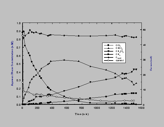
Figure 2. Results of a typical reductive dehalogenation experiment at an iron cathode (0.89
mM CCl4 ; 0.1 M Na2SO4 ; pH 7; EW -0.8 V vs. SHE).
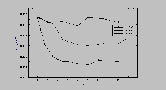
Figure 3. Dependence of kCT on pH and EW (at a Cu cathode).
Figure 4. Results of a typical oxidative dehalogenation experiments at an Ebonex
electrode ([TCE]0 1 mM; 0.05 M KNO3 ; pH 7). (A) Carbon mass balance (EW = +4.0 V
vs. SHE). (B) Chlorine mass balance (EW = +4.2 V vs. SHE).
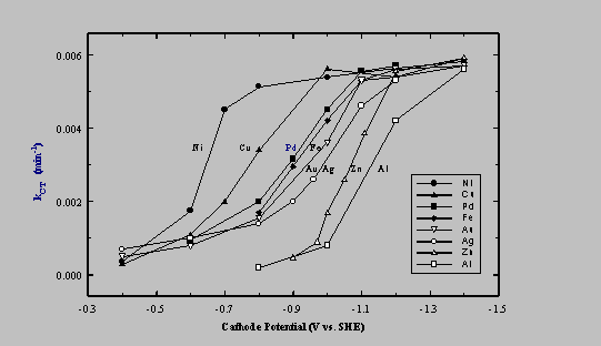
Figure 5. Dependence of rate constant on cathode potential, EW, (vs. SHE) and the nature of the metal for CT dehalogenation to CHCl3.
Figure 6. Dependence of the specific rate constant on anode potential, EW, (vs. SHE) for
TCE dehalogenation to CO2 and CO.
Figure 7. Proposed mechanism for oxidative dehalogentaion of TCE at an Ebonex anode.